
The kSA Glass Breakage & Defect Detection tool is a vision-based metrology system that determines Go/No-Go (Pass/Fail) conditions for every glass lite and panel it inspects inline during processing. The tool accomplishes this by comparing coated or uncoated glass lites and panels against user-defined parameters and tolerances in a master specification reference to identify defects such as cracks, chips, scratches, digs, and pinholes.
Details:
- The custom frame enclosure houses a linescan camera, LED lights, and photoeyes.
- The camera vision system captures images of the panels as they pass by the instrument on a conveyor.
- LED lights illuminate the panels to help distinguish between defects and minor irregularities.
- Photoeyes detect the leading and trailing edges of the panels to trigger the system to start and stop data collection.
- High-resolution encoders trigger spatially-resolved linescans as the panel moves under the LED lighting, generating a high-resolution image of the panel for detailed image processing and defect detection.
- The CPU provides image processing and data storage capabilities.
Benefits
Real-time visual and data analysis of glass breakage and defects (scratches, digs, cracks, chips, pinholes, etc.) to quickly quarantine or scrap inline defective product as it moves along the line.
- Early detection of defects results in reduced down time and scrap costs.
- Documented compliance with applicable glass visual and safety standards (ASTM, ANSI) ensures consistency across all glass lites and panels.
- Customizable software enables users to configure the settings to fit their specific needs.
- In-process QC validation ensures that all lites and panels conform to the custom master standard.
- Factory integration capabilities enable facilities to incorporate the tool into existing systems (factory alarms, PLC, email alerts, etc.).
Technology
The custom frame enclosure houses photo eyes, LED lights, and a single line-scan camera.
- Photo eyes detect the leading and trailing edges of the panels and trigger the system to start and stop data collection.
- LED lights illuminate the glass panels from underneath the conveyance system to help distinguish between defects and minor irregularities.
- The camera vision system captures linescan images to identify glass edge dimensions and then captures full area images of the glass lites and panels as they pass by the instrument on a conveyor.
- High-resolution encoders trigger spatially resolved line scans as the panel moves over the LED lighting system, generating a high-resolution image of the panel for detailed image processing and defect detection.
- The CPU provides image processing, data analysis, and data storage capabilities.
Capabilities
Provides high-resolution line-scan camera system options (up to 1,000 samples/second) to meet desired conveyance line speed and image resolution
- Captures high-resolution glass panel images and stores data for the user-selected lites and panels (failed, random, all, etc.)
- Handles both clear/transparent glass and opaque glass using high-intensity (>14K lux at 500 mm working distance) LED light bar modules with safety shielding
- Includes built-in Calibration/Gage R&R testing
- Starts and stops data acquisition based on triggers from the in-line photo eye detectors
- Allows skew of +/- 5° through the scanning process
- Supports conveyor line speeds ranging from 1 to 36 m/min (balanced against resolution/accuracy requirements)
- Scans clear or coated glass of thicknesses ranging from 2 to12 mm
- Supports tempered or heat-treated glass with distortion of +/- 15 mm
- Measures in situ panels up to 1.2 x 2 m (single camera system) with +/-0.5 mm accuracy
- Supports multiple-lite loads
- Applies a customized reference standard based on pass/fail limits on user-specified parameters and tolerances
- Captures, analyzes, and stores data using proprietary k-Space software
All of this is accomplished through the glass breakage detector, which includes the frame with detectors and standalone electronics cabinet with rackmount CPU, monitor, keyboard, and mouse.
Software
- Capable of acquiring data from a live source or a saved data file
- Capable of filtering or smoothing data using a variety of methods and parameters
- Able to write to SQL databases and files for off-line analysis with statistical software tools, such as JMP from SAS
The In Situ Film Thickness metrology tool is a non-contact, non-destructive, real-time thin film characterization sensor that utilizes the detailed spectral analysis of specularly reflected light from the solar panel. This system is designed to monitor film thickness directly on coater tools.
Details:
- Proprietary k-Space spectral fringe analysis determines semi-transparent thin-film thickness in real-time.
- k-Space software analyzes the below-gap spectral interference fringes to determine the total film thickness.
- The system acquires spectra data and determines thickness in real-time, all without interfering with the production line.
- Typical systems include 2 probes per tool (left channel and right channel).
- A sapphire reference normalizes the light source output.
- The tool detects panels through a threshold signal level (peak intensity of raw spectrometer signal).
The Inline Film Thickness and Roughness metrology tool is a post-coater metrology tool that analyzes the below-gap spectral interference fringes to determine the total film thickness. In addition, it determines film roughness by inspecting the envelope of the interference spectra.
Details:
- The system performs final film thickness and surface roughness measurements after the coating has been applied.
The software utilizes proprietary k-Space spectral fringe analysis.
- Typical systems include 2 probes per tool (left channel and right channel).
- The inline tool includes inline sapphire references that sit approximately 2mm below the bottom surface of the panels.
- The spectrometers are Flat-Field-Corrected (FFC) to ensure proper roughness measurement and tool-to-tool roughness matching.
- The tool detects panels through a threshold signal level (peak intensity of raw spectrometer signal).
The Transmission metrology tool measures transmission signal directly through the panel. It measures both material band edge (if present) and Integrated Band Absorption (IBA) values simultaneously.
Details:
The tool continually recalibrates between every panel by making a full transmission measurement between panels.
- An integrating sphere on the underside (transmission) collects all signal for proper, absolute transmission and IBA measurement.
- The tool detects panels through a threshold signal level (peak intensity of raw spectrometer signal below between-panel transmission signal).
- Standard systems include 2 probes per tool.
The negative PhotoResist metrology tool is a non-contact, non-destructive, real-time thin-film characterization system that measures nPR (negative PhotoResist) thickness via a thin film interference fringe analysis from the reflected spectral intensity profile. This is a delta thickness measurement that requires the tool to pre-measure the underlying base film thickness to determine the final thickness of the nPR.
The Absolute Spectral Reflection metrology tool measures absolute spectral reflectance to characterize various films, including anti-reflection coatings (ARC). The system utilizes a 340-930nm spectrometer. An internal quartz reference continuously calibrates the absolute reflectance between panels.
Details:
- The tool uses an internal quartz reference and beam splitting optics to recalibrate between every panel.
- The tool measures color information (L*a*b* parameters) and scales the values to the sun light output distribution function.
- The optional kSA FitTool simulation and fitting software adds the ability to determine film thickness.
- A sapphire reference normalizes the light output signal.
- The tool detects panels through a threshold signal level (peak intensity of raw spectrometer signal).
- Standard systems include 3 probes per tool.
The Panel Edge metrology tool utilizes high-resolution 406nm laser line profilers to measure the edge profile of the panel/module.
Details:
- The main parameters measured with this tool are edge radius of curvature, chip and crack detection and size, and debris detection.
- The system uses mountable, custom gauge blocks to calibrate each head for height and radius of curvature measurement.
- The tool detects panels through a threshold signal level (peak intensity from reflected laser line profile).
- Standard systems include 2 probes per tool.
The Panel Thickness and Warp metrology tool measures total panel thickness, bow, warp, and total thickness variation (TTV). The tool utilizes 10 Keyence laser-based height sensors (5 above and 5 below) to measure at 5 stripe positions along the panel.
Details:
- Colinear laser sensors determine the panel thickness by measuring the panel height on top and bottom. As such, vertical movement/bounce of the panel does not affect the measurement, b
ecause the delta height measurement accounts for the height offset.
- The software deduces bow, warp, and TTV measurements from the individual height measurements.
- Standard systems include 10 probes per tool (5 top and 5 bottom, for 5 stripe positions).
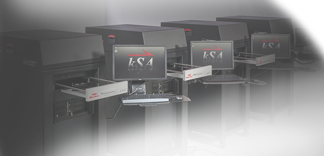
The glass industry has its own unique set of requirements that k-Space’s glass metrology can accommodate. There are needs for edge inspection, broken glass detection, glass thickness calculation, as well as film thickness, spectral reflectance, absorption, color (L*a*b*) measurement, to name some of the metrology needs.
Using state-of-the-art lasers, light sources, machine vision technology, and other tools, our product engineers, software engineers, and physicists can develop a solution that measures your specific need for glass inspection. This leads to better quality control, which in turn leads to happier end-use customers and improved yield.
The glass industry is continuously evolving and creating new products that are more energy efficient and that provide a healthier environment for building occupants, such as dynamic glass. When customers use our tools for applications such as these, they can be assured that each panel has an accurate measurement for color, reflectance, and other properties, which results in the best end product possible. Our tools also aid in the development of new processes and allow for the process optimization to keep costs down and quality high.
Each glass fabricator or manufacturer has their own set of manufacturing issues where they want to improve the yield or quality. Bring your glass measurement challenge to us, and we will engineer a custom metrology solution for you.