Application Notes : kSA BandiT – Analog Output Configurations
Version: 1.0
How to configure kSA BandiT analog outputs

The kSA BandiT system supports various data acquisition boards for real-time analog output. It allows for custom configuration of these boards for a particular process control and/or data logging application, including mapping the output channel(s) to a suitable voltage range. This tech note describes the steps required to configure kSA BandiT for such an application. For more information see the kSA BandiT user manual.
1. From the Options menu, select Input/Output Devices…

2. In the Input/Output Device Options dialog, select the Analog Output Board tab. From the dropdown menu, select the model of the board present in the system in question. Most systems use the ACCESS IO USB-AIO12-16E 0-5V board which is referenced in this example. For each of the desired output channels, verify that the Voltage range is set properly (0-5V in this case). Also verify that the proper Control channel is selected. Channel 0 is most commonly used, as it is wired to the BNC connector on the back of the kSA BandiT rack.
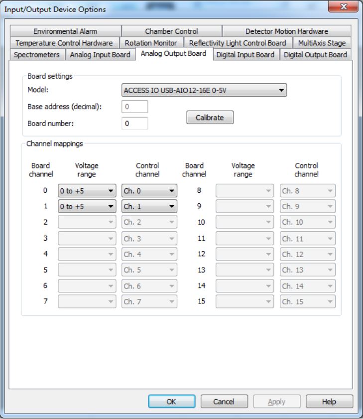
3. Select OK to close this dialog.
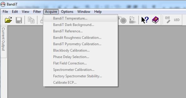
4. From the Acquire menu, select BandiT Temperature…
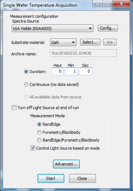
5. In the BandiT Temperature Acquisition dialog, select the Advanced… button.
6. In the Advanced Acquisition Options dialog, select the Device Output Control tab. Select the Enable device output control checkbox. Then select the Edit output mappings… button.
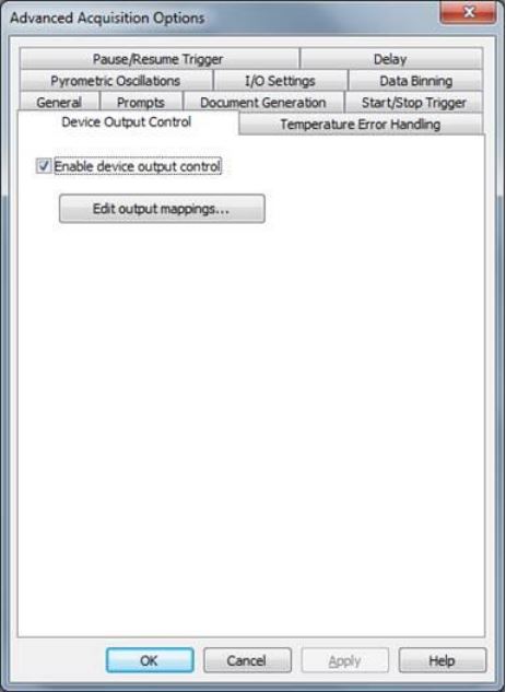
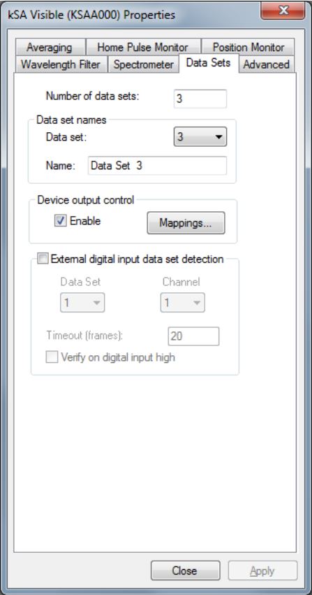
Note that in kSA BandiT Multi-Wafer, this is located in the Data Sets tab found in the spectrometer settings dialog, which is accessed by right-clicking on the live spectrometer window and selecting Properties…
7. In the Device Output Control Mappings dialog, enter the following settings for each of the desired
output channels:
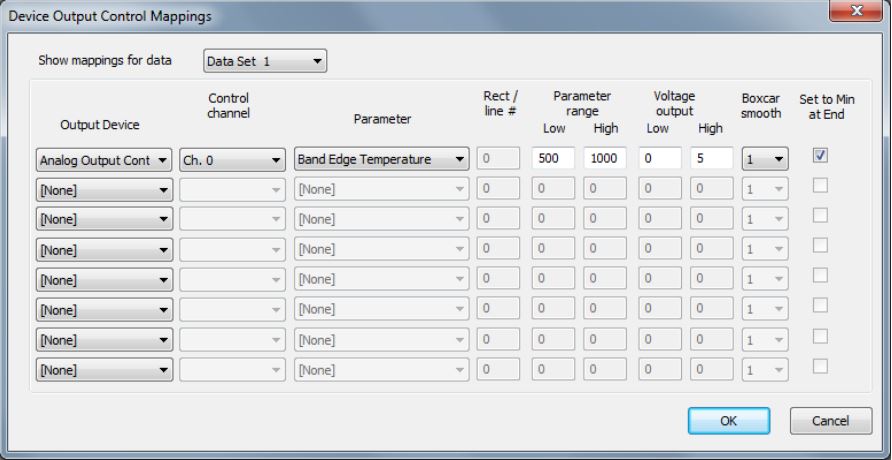
- Select the desired output Parameter from the drop-down menu. Note that one can select from a variety of different parameters.
- Enter the desired Parameter range and Voltage output range.
- The Boxcar smooth dropdown box allows for smoothing of the output using a moving average, a.k.a. boxcar. A setting of N results in each data point being averaged with the (N-1)/2 neighboring data points on either side. Note that N must be odd. The default value is 1, i.e. no smoothing.
- The Set to Min at End checkbox will force the output to go to the minimum value (0V in this example) at the end of the acquisition.
- Note that the data set selection applies only to kSA BandiT Multi-Wafer, in which each marker is assigned a separate data set. In that case, only information corresponding to the specified marker(s) is output. For more information see the kSA BandiT user manual.
8. Select OK to close this and the Advanced Acquisition Options dialog.
9. Note that there may be times when it is advantageous to adjust the output mapping to achieve
greater resolution.
- For example, consider the case in which the kSA BandiT output (typically 0-5V w/16 bits) is connected to a typical 12 bit ADC with a fixed 0-10V input range. In this case, the smallest voltage step that could be resolved by the ADC is 10V/4096 = 2.44 mV. If one were to simply map a temperature in the 0-1000°C range to kSA BandiT’s 0-5V output, the scaling factor would be 5 mV/°C. Given the ADC’s resolution of 2.44mV, the smallest temperature step that could be resolved is 2.44mV / (5mV/°C) = 0.49°C.
- If instead, one were to adjust the mapping such that 500-1000°C corresponds to the 0-5V output, the scaling factor would now be 10 mV/°C, and the smallest temperature step that could be resolved would be 2.44mV / (10mV/°C) = 0.24°C. Thus a greater resolution could be achieved in exchange for a reduced range. This is often a good trade-off, as most users are only concerned about a relatively small range around the process temperature.
- Note that one should always verify that the ADC to which kSA BandiT is connected is set for the correct voltage to temperature mapping. In the example above, the 0-10V ADC input would correspond to 500-1500°C. Of course, the BandiT output would never go above 5V with the board used in this example.
- Also note that if a higher maximum temperature is desired, one could simply shift the mapping, say to 750-1250°C, for example.